Pixel Padding and Bleeding Detection in 3D Modeling
This article discusses the problem of maintaining pixel padding and creating an algorithm for detecting it. We are not going to focus on the code itself but rather on the core principle of pixel padding, which can be implemented in any language and in any development environment.
The Basics of Pixel Padding
A request for a 3D model includes, as a rule, requirements for the texture resolution. Because of bitmap discreteness, a 3D artist must maintain a distance between the parts of a texture map. This technique is known as pixel padding, edge padding, or UV padding and is necessary so that a pixel will not be rendered on the model in completely different places than it should be.
It is especially important to control the proper distance in the early stages of work. Typically, one person carries out geometry development, which includes texture mapping, and another person is responsible for texture design. An error detected by a 3D artist will cause less trouble than one discovered by a texture artist. The latter case becomes even more complicated if the 3D toolset being used – say, a brush – does not provide options for drawing over the geometry.
There are two situations where more space may be required between map elements. In the first, texture resolution is reduced as a result of mipmapping. The second entails the use of a dilation filter at the lightmapping stage. When performing UV mapping, a 3D artist should adhere to the requirements for texture resolution and also consider the aspects discussed in the first part of this article. However, some issues still go unnoticed without automated error detection.
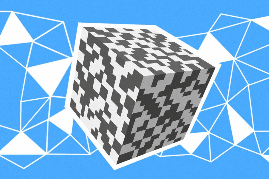
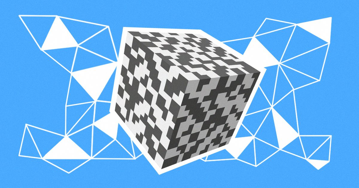
Example of the emergence of artifacts when resolution decreased
A texture map for simple models can be formed using automatic tools. But these tools are based on internal metrics and do not take pixel padding into account, so the shared pixels are often located along the diagonal boundary lines. A review using checkered textures does not show all the errors, and these textures often have a higher resolution than those that will be used later in the project.
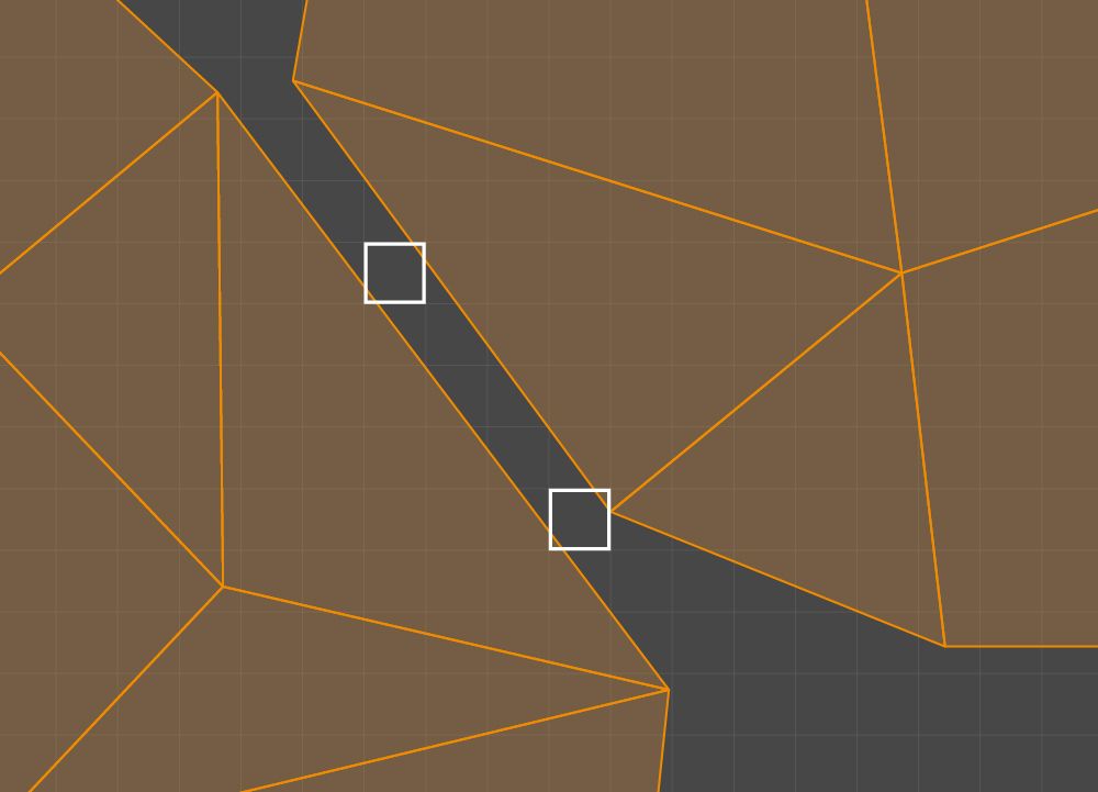
Shared pixels marked in white
The problem of insufficient pixel padding in UV mapping is similar to the problem of overlapping. Both can be responsible for so-called bleeding.
However, the pixel padding problem depends on the required minimum texture resolution. Checking the resolution once is sufficient to detect any overlapping, though the required texture resolution may change at the next stage of development. The situation becomes more complicated because the 3D modeling software that Plarium uses does not provide any tools for the automatic detection of errors related to the proximity of UV mapping parts. And one should bear in mind that after the automatic mapper in Unity finishes its work, UV2 error detection is required.
We decided to develop a tool capable of checking pixel paddings and marking the areas on the model where issues are likely to arise. The calculation of the required padding is based on the following parameters:
- Basic texture resolution
- Minimum texture resolution that prevents bleeding
- Required padding on the minimum texture
Given that the sizes of our applied textures are equal to a power of two, a formula for calculating the required padding at the basic resolution is quite simple: (BasicResolution / MinimumResolution) x PaddingOnMinText.
The solution to this problem is obviously connected to rasterization, as explained in the next section.
Key Concepts
Here we introduce some concepts to specify the requirements and develop the algorithm.
Consider UV space and a uniform mesh with N x M dimensions in the range 0.0–1.0. Cells 1/N wide and 1/M high split the UV space into a grid.
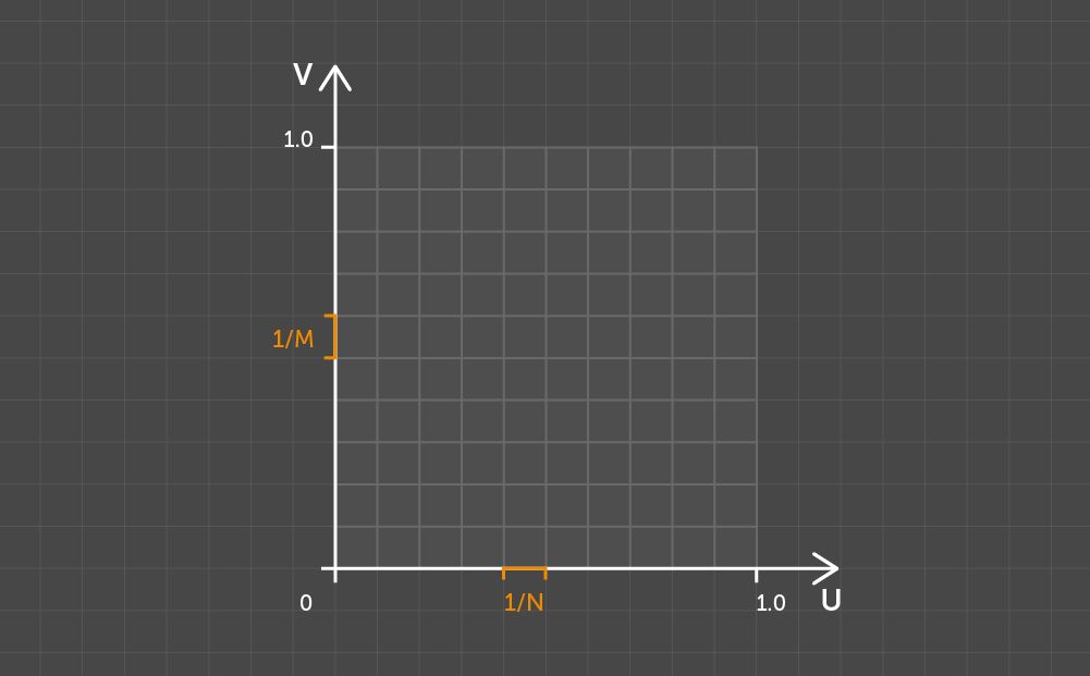
Splitting the UV space with N x M
Take two arbitrary points and use Dn to indicate the number of pixels occupied by the projection on the U axis of the line segment connecting the given points. Use Dm for the V axis in the same way. Then define the pixel distance as the maximum distance between Dn and Dm.
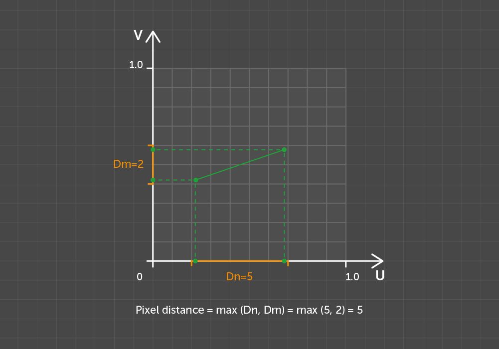
Pixel distance between points
Note that if the pixel distance is used as a metric, motion operations such as parallel translation and rotation cannot be the motions for the grid in Euclidean space. This nuance added some complexity to the development of our solution.
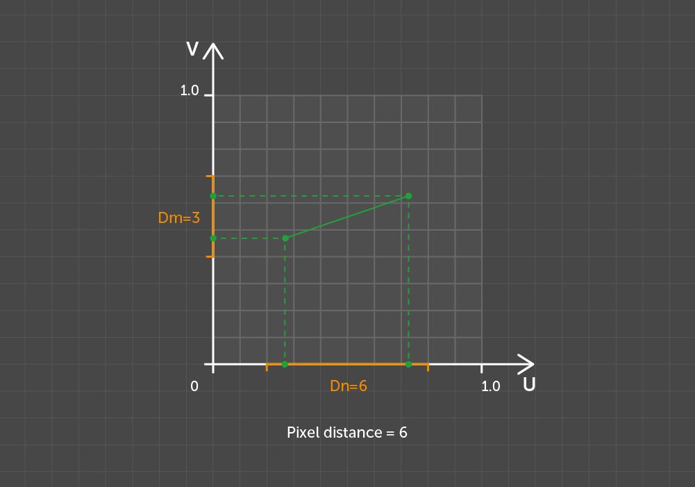
Pixel distance between the same points but with an offset
Let a square with a side of K pixels be a K-size kernel. Then any two points with a pixel distance of less than K between them can be overlapped by a K-size kernel.
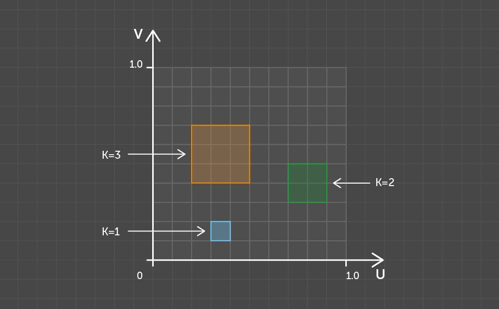
Examples of kernels of different sizes
Two edges of the polygon form the concavity of the outline if their midpoint (the center of mass of four vertices) is located to the left of these edges when traversing the outline in a clockwise direction. From a counterclockwise perspective, the point is to the right of the edges.
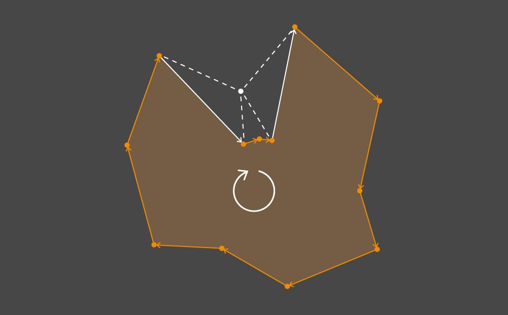
A pair of edges forming the concavity of the outline
Solution
Now we can talk specifically about checking the pixel padding. To perform this task, we have developed an algorithm composed of three independent phases. The sequence does not matter. Each phase activity results in an N x M matrix that represents the grid cells’ buffer, where some cells are marked. By adding all three buffers together, you get the overall result.
Let’s start with the simplest phase. It is designed to look for cells that intersect with almost degenerate triangles and with edges whose length is less than the side of a kernel of a given size. All such cells are marked within the buffer.
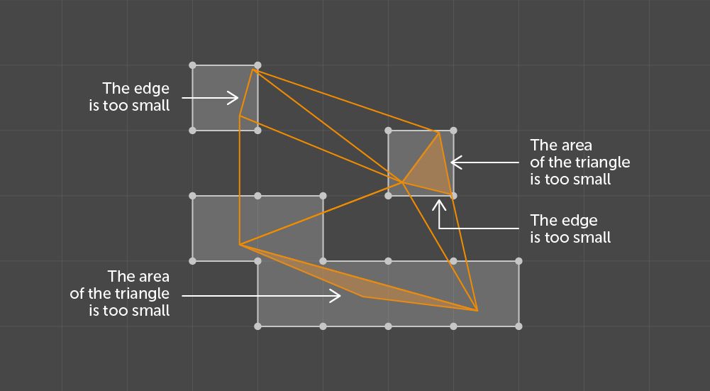
Results of checking the size of components
Before discussing the other two phases, let’s take a look at how they work in general. Both are engaged in processing the clusters within triangles called shells or islands. For a 3D artist, a shell is a connected set of polygons – that is every polygon in the set shares its vertices with an adjacent one. An independent polygon is also regarded as a shell. Hereinafter, we shall use the terms shell, island, and cluster interchangeably.
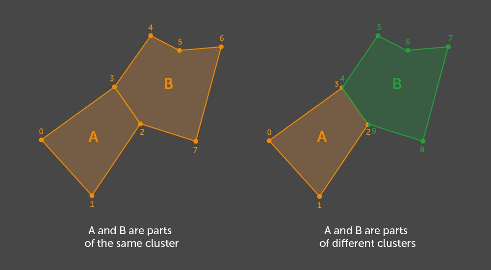
Example of clustering for two polygons - with and without shared vertices
In order to find all the shells, we use our algorithm. This algorithm searches all the graph connectivity components where a graph node represents a polygon and its edge is introduced through the existence of at least one vertex which is shared by a pair of polygons. Because the only Unity polygon in use is a triangle defined by its vertex indices, we treat other triangles as adjacent ones if at least one of their vertex indices matches that of the given one. If we take into account the similarity to the graph and the method for determining the edges, we see that a set of vertex indices in one cluster does not intersect with a set of vertices in the other cluster.
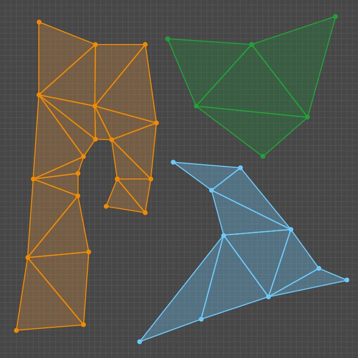
Example of clusters of triangles
The second phase under review identifies possible errors related to the proximity or overlapping of various clusters.
As input, we have multiple clusters represented by sets of triangles on the UV space, grid sizes matching the corresponding texture resolution (N x M), and a padding value P as a number of pixels. Within the given grid, one must find the areas where the pixel distance between the clusters is less than the required padding. A cell in the output matrix is marked if it is included in at least one kernel of the size K = P + 1 that intersects two different clusters.
The output description presents a good indication of the key operations of this phase. All the K-size kernels that intersect with the triangles from different shells and the cells of these kernels should be marked in the output buffer.
Within our implementation, we review all pairs of clusters sequentially. For each pair, we find the intersection of sets of K-size kernels which are overlapped by these clusters. We then choose a pair and define that set as Q.
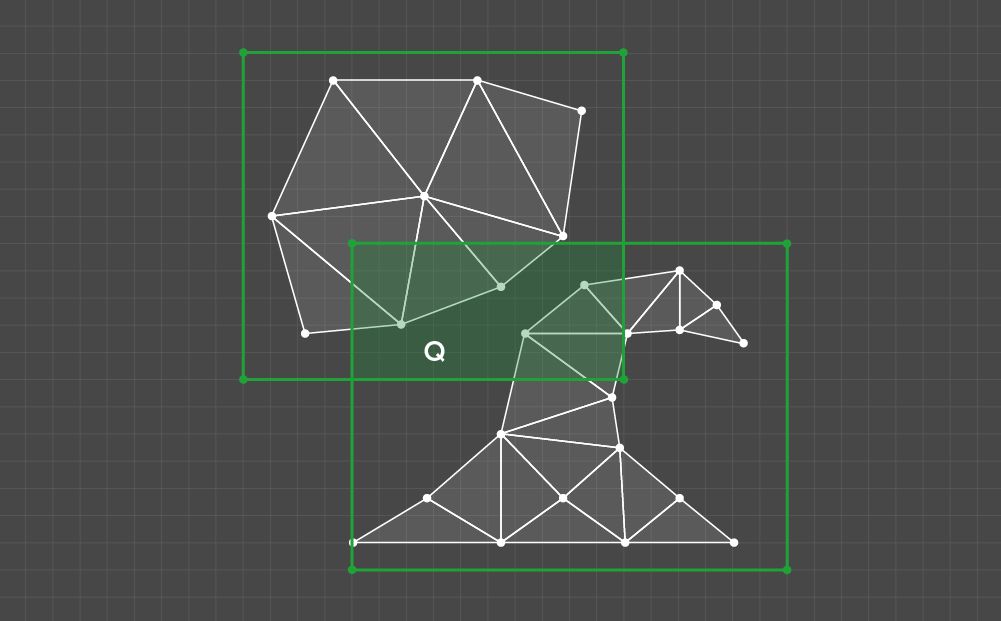
Example of a Q set
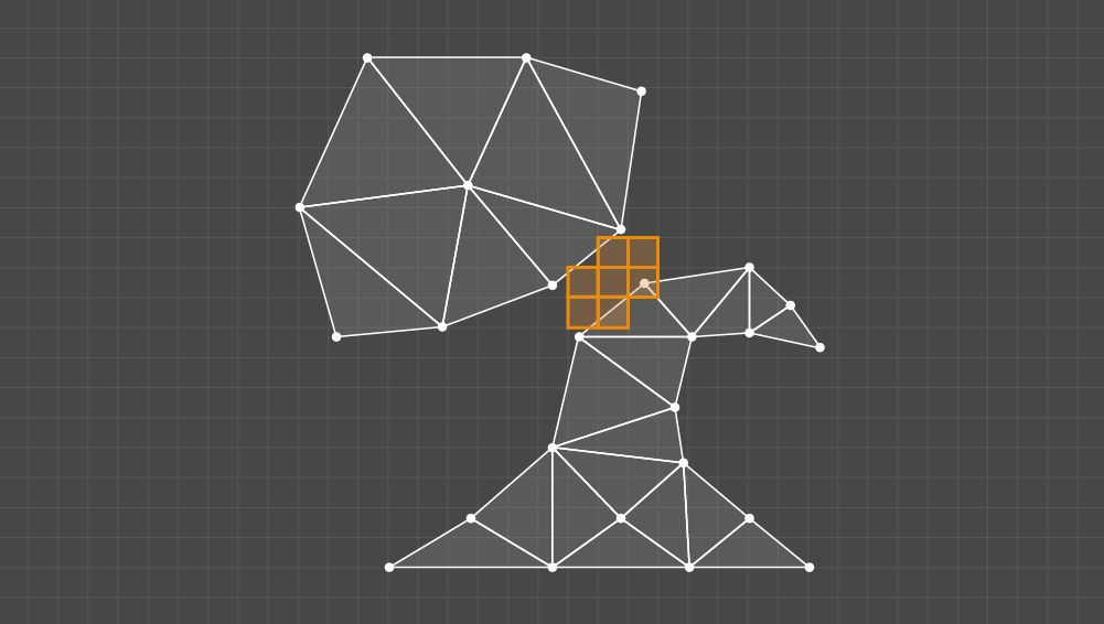
All Q elements should then be tested according to the one criterion: whether the kernel intersects at least one triangle in every cluster of the given pair. If so, all the cells of the testable kernel should be marked.
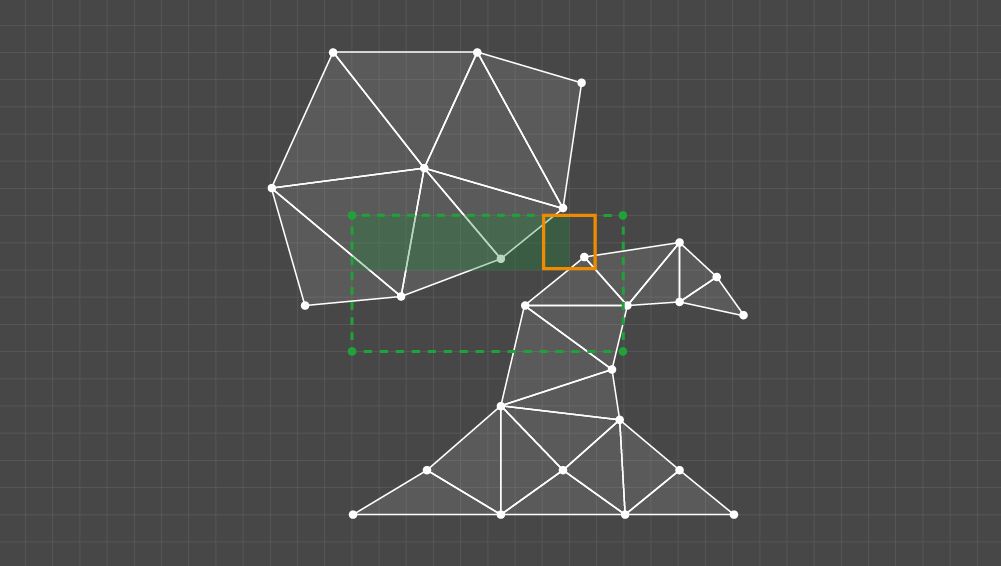
Example of kernels processing
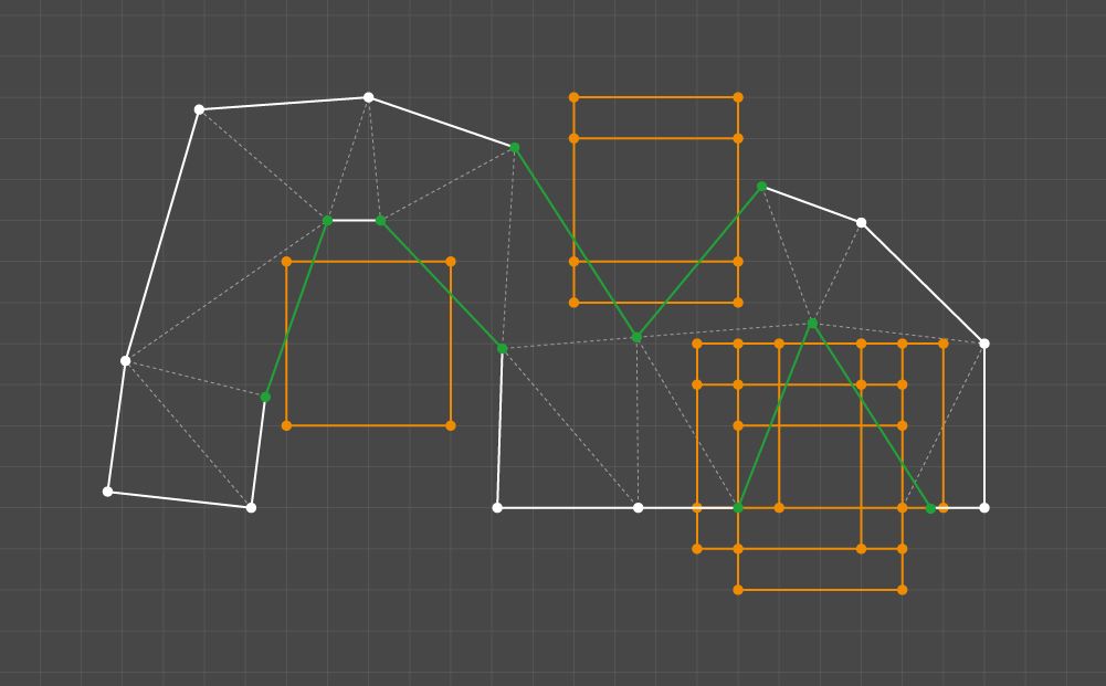
The result is a buffer with marked cells for all pairs of clusters.
Result from checking the distance between the clusters
Now we have come to the last phase. Here, a single cluster needs to be processed. As input, we have a set of triangles in the UV space, grid sizes matching the corresponding texture resolution (N x M), and a padding value P as the number of pixels. The cell can be marked in either of two cases: the pixel distance between concave edges is less than the required padding, or the cluster is invalid or has holes.
We are not interested in the inner part of the cluster; we have to obtain its outline, represented as a linked list of edges. Adjacent triangles duplicate the vertex indices; thus, the edge belongs to the outline if a pair of its vertex indices is unique for a set of cluster edges. Once you know which edges form the outline, put them together to obtain a linked list.
If, after this step, some edges of the outline remain unlisted, the cluster apparently has holes or there is an error in the mesh data. In this situation, you need to mark all the cells of the kernels that are intersected by the cluster.
If the outline is identified, the processing continues. We have formulated the following output requirement: let a pair of edges that form the concavity of the outline intersect the K-size kernel = P + 1; if both parts of the outline between the edges go beyond the kernel boundaries, then the kernel’s cells should be marked.
Specific features of the cluster and the results of their examination
We decided to satisfy this requirement through a pair-wise comparison of the outline edges. Concavity is checked as the first condition, and then, for each pair, all the kernels that intersect both edges are checked. Checking a kernel requires that each part of the outline between a pair of edges is traversed. If each part contains at least one point beyond the boundaries of the kernel, all the kernel cells should be marked.
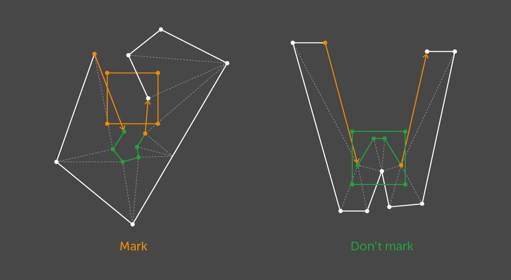
Example where the cells of the testable kernel should be marked
Outcome
The algorithm shown here is well suited to implementation through parallel computing. Each pair of clusters and edges is processed autonomously. Because the tests are based on rasterization, it is reasonable to use GPU capabilities if we start from the kernels instead of a pair of edges.
The next step is to transform the algorithm output into a texture. Within the given resolution, this procedure enables potential errors in UV mapping to be displayed in graphic form. The resulting texture can be applied to the model to represent the marks directly on the geometry.
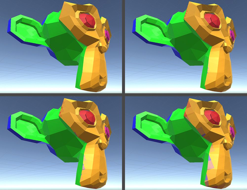
As shown in the images below, we cut a rabbit and Suzanne with Blender, an automated tool, to obtain more artifacts. The texture resolution to be tested is set at 256х256, with a required distance of 1.
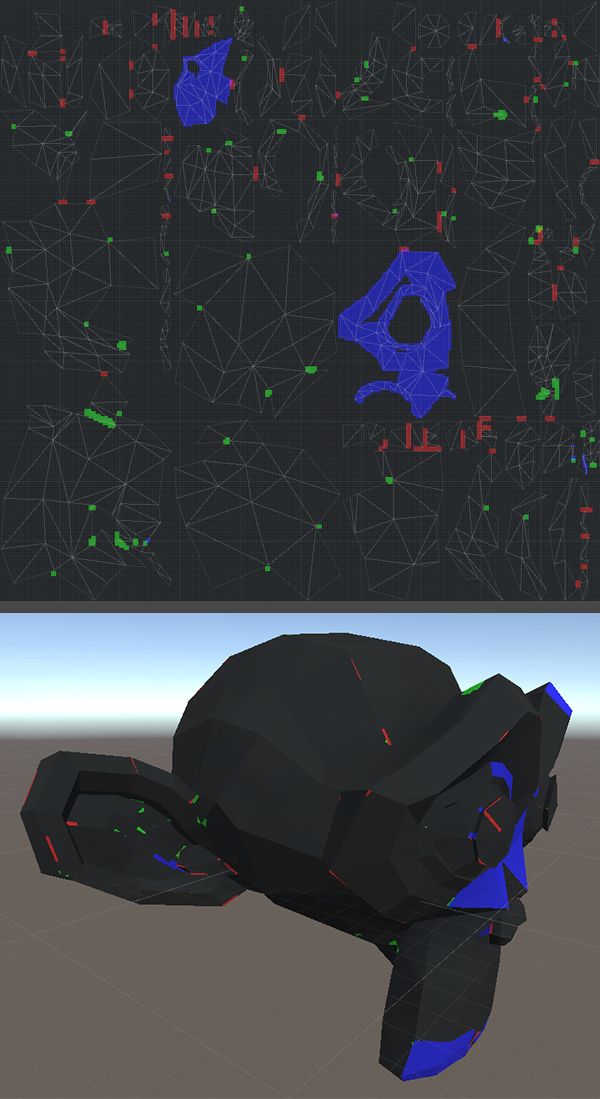
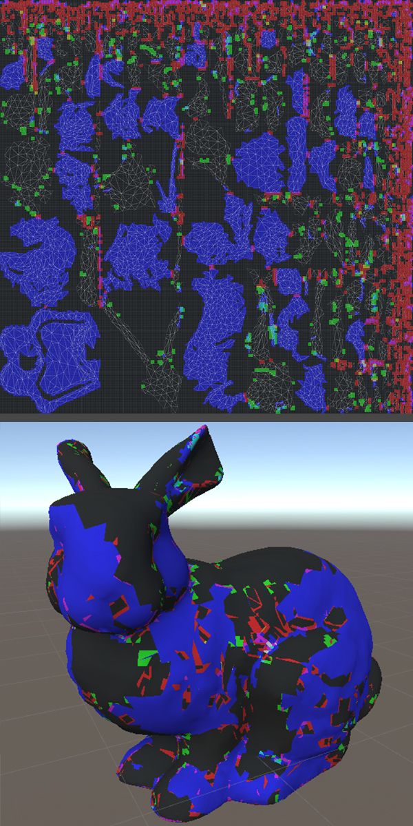
Examples of the algorithm applied in Unity
Blue cells, excessively small triangles, and edges, cover the clusters with holes. The cells of kernels with specific features of every single cluster are green. Kernels that do not observe the pixel padding between clusters are red.